Small Commercial Facility Power Distribution Design and Analysis
Preliminary 12.47 kV-to-208/120 V radial distribution study for a synthetic 35,000 ft² office and warehouse.
Executed simulation
Analytical calculation
Automated test
Problem statement
Develop an explainable small-facility distribution architecture and test whether preliminary transformer, feeder, and panel choices remain acceptable across normal and stressed operating conditions.
An executable educational design that connects a load schedule and preliminary equipment sizing to AC load flow, voltage-drop checks, phase allocation, and fault-current analysis.
331.4 kW
Base source power
Executed balanced AC base case
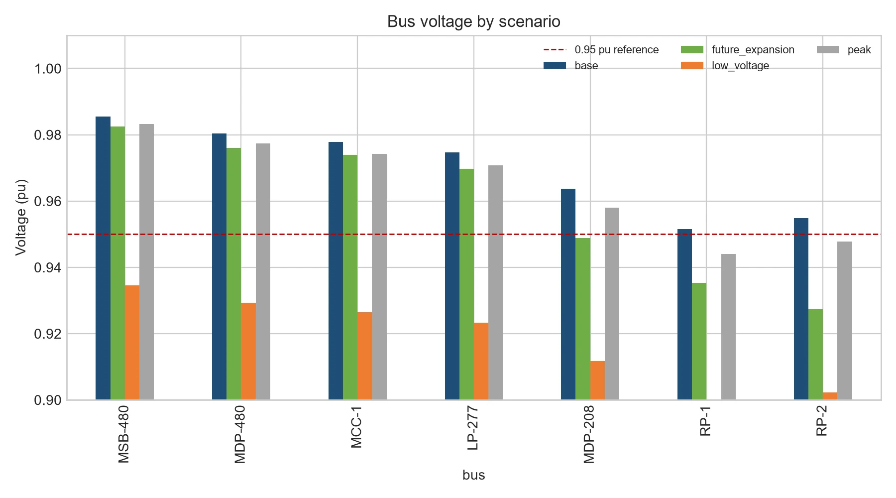
0.952 p.u.
Base minimum voltage
Barely above the 0.95 p.u. planning target
0.927 p.u.
Future minimum voltage
110% existing load plus 30 kW future allowance
16.2 kA
Maximum 3-phase fault
Modeled at the 480 V main switchboard
Project scope
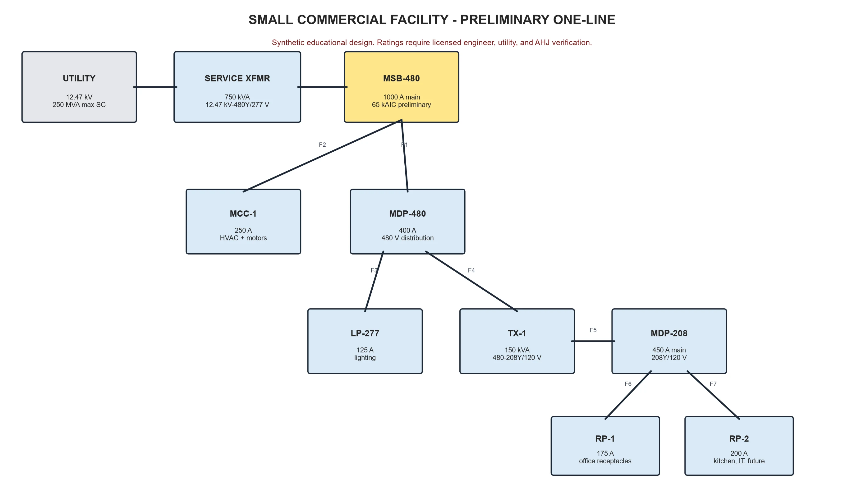
12.47 kV utility equivalent, 750 kVA service transformer, and 480Y/277 V distribution
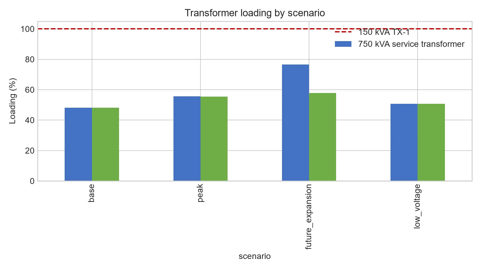
150 kVA derived 208Y/120 V system for receptacle, IT, kitchen, and future loads
Synthetic load schedule, feeder assumptions, four operating scenarios, and preliminary protection hierarchy
Balanced positive-sequence analysis; not a construction or permit design
System or processing architecture
A radial utility-to-service-transformer topology supplies a 480 V switchboard, motor and lighting panels, and a downstream delta-wye transformer feeding two 208/120 V panels. Phase allocation is checked separately from the balanced network solution.
My engineering contributions
Built the load schedule and translated connected kW, demand factors, and power factor into kW, kvar, kVA, and current.
Implemented the pandapower network, scenario runner, IEC 60909 three-phase fault study, and result exports.
Used execution results to correct an undersized upstream feeder and improve single-phase load allocation.
Produced the one-line, calculation workbook, engineering report, validation checklist, and hand-calculation checks.
Important design decisions
Used 480 V for larger three-phase loads and 277 V lighting to limit current while deriving 208Y/120 V for common utilization loads.
Selected a radial topology so load paths, protection boundaries, and failure assumptions remain inspectable.
Kept the single-line-to-ground value explicitly approximate because utility and equipment zero-sequence data are unavailable.